Having introduced the idea of a series of articles on “fun problems” earlier today, let’s get the first one out of the door: How to tetrahedralize an unstructured mesh that contains pyramids, wedges, and hexes, into a mesh that contains only tets, and in a way that one does not lose any shared-face connectivity in the output mesh. Most of the unstructured meshes I dealt with in the past have been “pure” tetrahedral meshes, but more recently more and more of those I encountered in any unstructured-mesh visualization projects also contained wedges, pyramids, and hexes – sometimes because those are natively the most obvious choices (eg, in the Agulhas data set multiple water depth layers for a triangulated ocean surface nativly form wedges, etc), and sometimes because the dual mesh of a structured AMR data set actually contains pyramids, wedges, and hexes, … so there we are. Maybe the most prominent example of such data is the NASA Mars Lander Retropulsion study data set that they recently released – almost all tets, but a few wedges thrown in, too. But since triangles and tets are so much easier to deal with, the most obvious choice for such data sets (if only for comparison purposes) is typically to simply tetrahedralize them into a tet-only mesh.
Now: Why is this tricky? After all, splitting an given wedge, pyramid, or hexahedron into tetrahedra isn’t all that complicated (in fact, I actually do remember that as a toddler I had toy puzzle with colored plastic tetrahedra that did just that!). After googling for solutions to that I found that you can actually also split a tet into five tets (rather than the obvious six ones), but that aside, the basic concept of tetrahedralizing such unstructured meshes isn’t all that complicated.
The problem, in fact, comes in through the back-door, if one innocently expects this tetrahedralization to maintain proper face connectivity: ie, if two elements shared a face in the input, we want the generated tetrahedra to also share faces in the output. For those faces in the input mesh that were triangle faces — ie, the four faces of any input tet, the four sides of an input pyramid, and the front and back sides of a wedge — that’s actually not a problem: those are triangles, and those won’t change. For those faces that are quadrilaterals, however — ie, the the base of a pyramid, the left side, right side, and bottom of a wedge, or the six faces of a hexahedron — it’s a bit more complicated: if the element itself gets split into tets these sides will, by necessity, have to end up as pairs of triangles… and there’s two ways of doing that, based on which of the two opposing pairs of vertices in that quadrilateral one ends up connecting.
Now if both elements that originally shared a quadrilateral face do this split in exactly the same way then both elements would end up with the “same” pair of triangles, so each triangle from the one element will have a matching one from the other one, and all is good. If, however, those two adjoining elements end up splitting that face in different ways, then the one’s triangles will not match the other ones, which can be, ahem, “problematic” for all the kind of algorithms that assume that each face can tell what the neighboring tet on the other side of that face would be (e.g., for face-to-face ray marching, or for the “shared faces” method in our 2019 “RTX Beyond Ray Tracing” paper).
In fact, even for algorithms that do not need to know this “neighbor on the other side”, ending up with an inconsistent way of splitting these shared faces can result in nasty surprises: quadrilateral faces in an unstructured mesh do not (!) have to be planar, but can actually be general bilinear patches (to visualize this imagine a hexahedron that’s a perfect cube, then take one of the vertices and pull it into an arbitrary direction …. then the three faces adjoining that vertex will become curved, bilinear patches). Now if two elements share a bilinear patch but split that into two triangles with different edges, then the resulting tet-mesh would either have a gap between these elements (if both chose the inward-flipping edge), or both elements would overlap in a tet-shaped region (if both flip outwards … and in case you were wondering: one going inwards and one going outwards only happens if they select the same edge).
Though this problem is kind-of obvious once one thinks a bit about it, I actually had to learn the hard way; most illustrations of wedges and hexes show only planar faces, so it took me a while to figure out why rendering my first tetrahedralized meshes seemed to produce some nasty “pockets” of empty space. Well, learned that one, didn’t we?
Anyway, i digress again. How to fix that problem? First obvious idea is to just make sure that all pairs or elements that share a face will always flip the same way; e.g., by always placing the edge into the vertex with the smallest index, or always picking the shorter of the two edges, etc. Again I spent quite a while trying to do just that, only to realize that this isn’t actually that trivial, either: to do this one would have to be able to independently choose the edge orientation in any of a hex’s faces …. but you can’t do that because at least one pair of opposing faces in a hex always has to have the same orientation (in case you’re wondering: tetrahedralizing a hex works by first using a diagonal plane to split it into two wedges, but that means that the two opposing faces split by that plane will have the same edge orientation….). Now I’m sure there’s a global optimization problem somewhere in there that would allow to somehow rescue that idea, but at that point I realized that this is a good deal more tricky than initially thought.
So, what else to do? Instead of always splitting each quad face with an edge into two triangles, I decided to instead insert a new vertex into the center of each such face, and split it into four triangles by connecting this new vertex to the four edges of that face (for unstructured meshes with scalar per-vertex data we obviously also have to interpolate the scalar values for this new vertex). The obvious downside of this is that one has to create some new vertices, which has all kind of issues (more vertices, more tets, more memory; the need to interpolate scalar values, etc) …. but if we’re willing to do that we can guarantee that any shared bi-linear patch will always end up with the same four vertices.
Having decided to do this for the faces, the next question is how to actually tetrahedralize the elements such that the faces will end up with this pattern. Here some little illustrations:
First, a tet will obvious remain a tet, no changes whatsoever.
Second, let’s look at a pyramid, which has exactly one bilinear face (see sketch below this paragraph, red and blue faces just for illustration): We create a new vertex C in the center of this face (by averaging vertices 0,1,2, and 3; green arrow), then connect this new vertex with the top (4) and the four base vertices (0-3, new edges in green), and and up with four nice tets that, on the bottom face, create exactly the pattern we’re aiming for (green for new edges on that face). Perfect.

(and, yes, i absolutely did steal my kid’s school pencils for this awesomely professional illustration… and free-hand sketching is so much faster than all the fancy programs!)
Third, let’s look at a wedge with front face 0,1,2 (blue) and back face 3,4,5 (red). We now have three quadrilaterals to deal with, for each of which we want to have the “four triangles” pattern described above. Luckily, there’s an easy way to create just that: we simply ignore the faces completely, and create a new vertex C in the center of the wedge (again, by averaging); now if we connect this new vertex to the existing five faces we end up with two tets (C to front and back triangle), and three pyramids (C to bottom, left and right quadrilateral). For the pyramids we do the same as described above, so our desired pattern appears on all quad faces of our wedge, too … perfect.
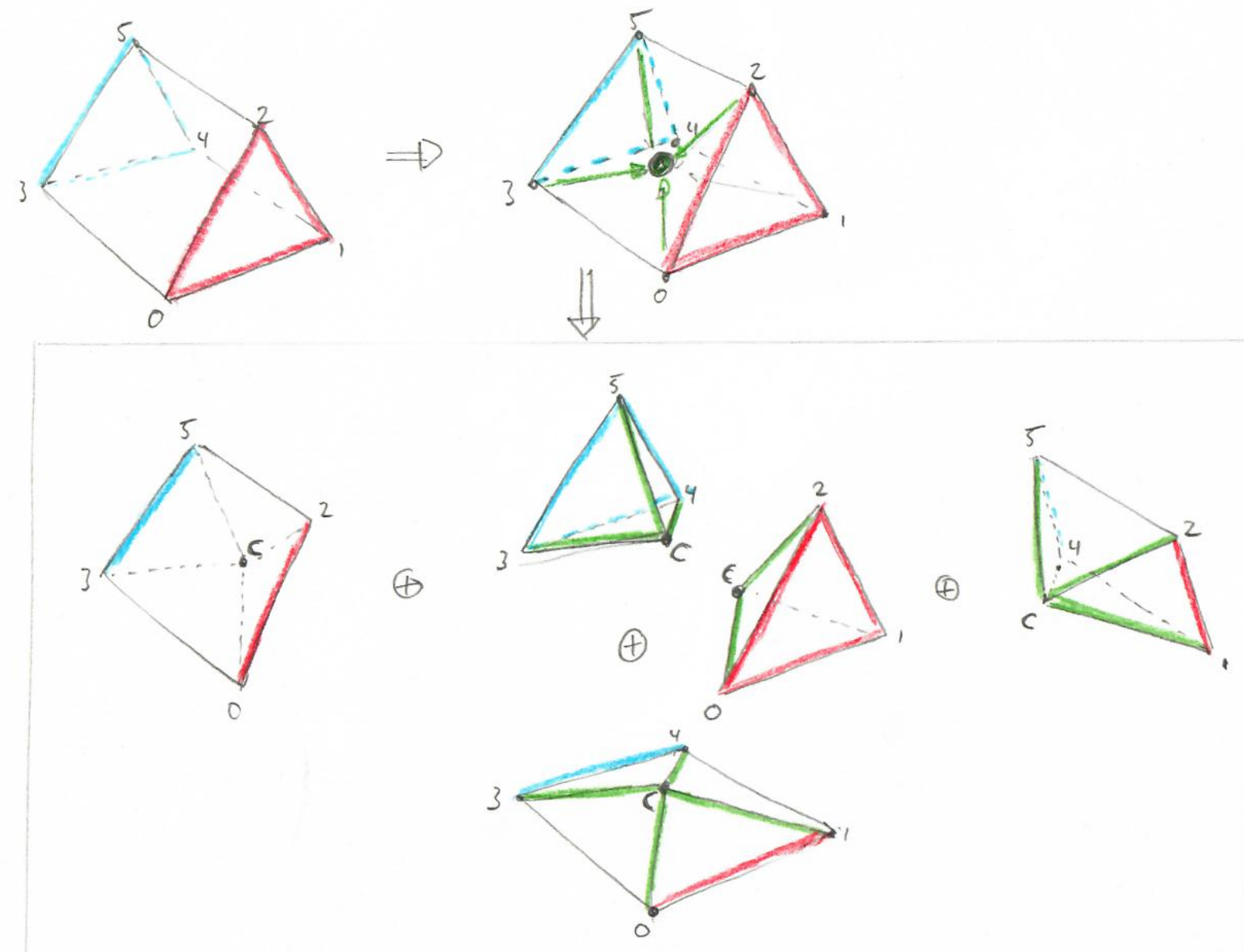
One will obviously have to further subdivide the three pyramids in this sketch (ending up with a total of 16 tets), but that got too much to draw …. and should be obvious.
Finally, compared to the wedge case the hexes are almost trivial: create a center vertex C, then connect it to the four faces, and get four pyramids …. feed those into step 2, and done.

All in all, that algorithm is trivially simple to code up (oh, if only I had found that one earlier ….). Only one thing to consider: thanks to limited floating-point accuracy it is, in theory, possible that two elements sharing a face might end up with slightly different results for the center vertex, which might then throw off the code to find the “matching” triangles. This can, however, easily be avoided by always sorting the four vertex indices before adding the vertices, in which case both elemens would always perform the same computations, and up with the exactly same vertex (note we only have to do that for the face vertices, the inner vertices in the wedge and hex case are only ever created once, anyway).
As said above, the algorithm is simple, and foolproof; the main disadvantage is that additional vertices require more memory, and compute more tets, than tessellating without introducing new vertices. For example a hex can be represented with as few as 5 tets… but in our method it would create 24.
Hope that whoever found that page found it useful – I only wish I had found one like this before I tried the other routes. I wouldn’t be surprised at all if lots of people had done exactly that before, too … in fact, I’d be surprised if nobody did…. I just couldn’t find it. Any comments, suggestions, or issues with this: let me know!
PS: Fun fact – this all started with “just” needing to produce some more testing data for our “RTX Beyond Ray Tracing” paper – why not simply take an AMR data set (that we had plenty of), compute the dual mesh, and then tetrahedralize the result … can’t be that hard, right? Well …
