Finally, the day’s arrived: I’m hereby officially “introducing” OWL to the world.
This post is long overdue – I’ve already mentioned / hinted at OWL in previous posts (in fact, we already used an cited it in several papers), but have never yet actually posted or written about it, yet: initially, I didn’t want to write about it before it was “ready enough” for public consumption; then later, I got too busy using OWL for my own projects … and the more we did with it, and the more features it supported, the harder it got to find a good place to start talking about it.
Anyway; I finally tagged OWL as version 1.0 last week, so it’s about time to write a bit about it.
What is OWL?
OWL is, as the title of this post suggests, a “node graph” abstraction layer on top of OptiX 7. To be clear, OWL is not a “renderer” on top of OptiX (such as PRBT is), nor is it real-time “rendering engine” on top of OptiX 7 (as, for example, OSPRay is one on top of Embree); instead, it’s sole purpose it to take all the features of OptiX 7.x, and add a little bit of “magic” on top of it, in order to:
a) make it easier to get started with – and to properly use – OptiX, RTX technology, and hardware accelerated ray tracing; in particular for those are not the kind of “Ninja”-level RTX practitioners that can define the proper data layout and element ordering of a Shader Binding Table (SBT) at 3 am in the morning. Somebody recently decribed OWL as “training wheels for using RTX”; and though I think it’s more than that, it’s still a good picture.
b) to make it more productive to use OptiX 7 and RTX ray tracing, even for those that do dream about SBTs at night (yes, yes, I know…) – by automating some things that do need to get done in any OptiX program, but that the user really shouldn’t need to worry about, such as building the SBT, acceleration structures, etc. By making some of the more common (but time-consuming and bug-prone) tasks simpler for the user, the user can concentrate on what he/she really wants to do (the shader programs that implement the renderer!), not the care and feeding of device buffers, acceleration structures, and SBTs. E.g., once all geometries and groups have been created, building a shader binding table in OWL (even if you have no clue what it is) is as simple as calling “owlBuildSBT()”.
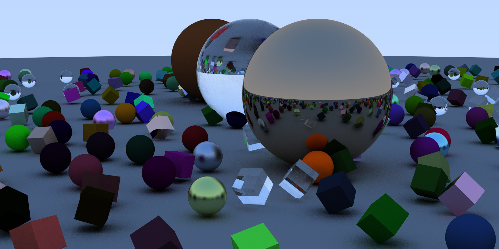
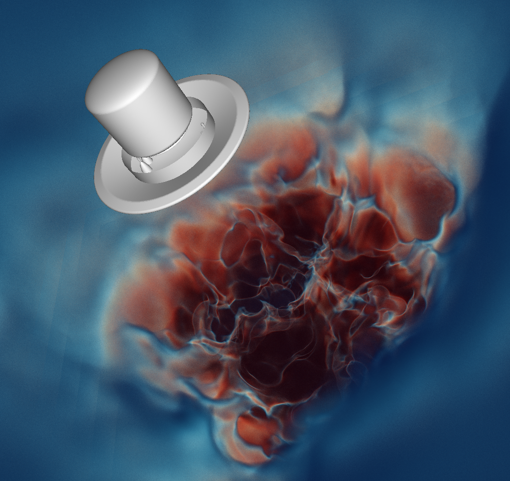
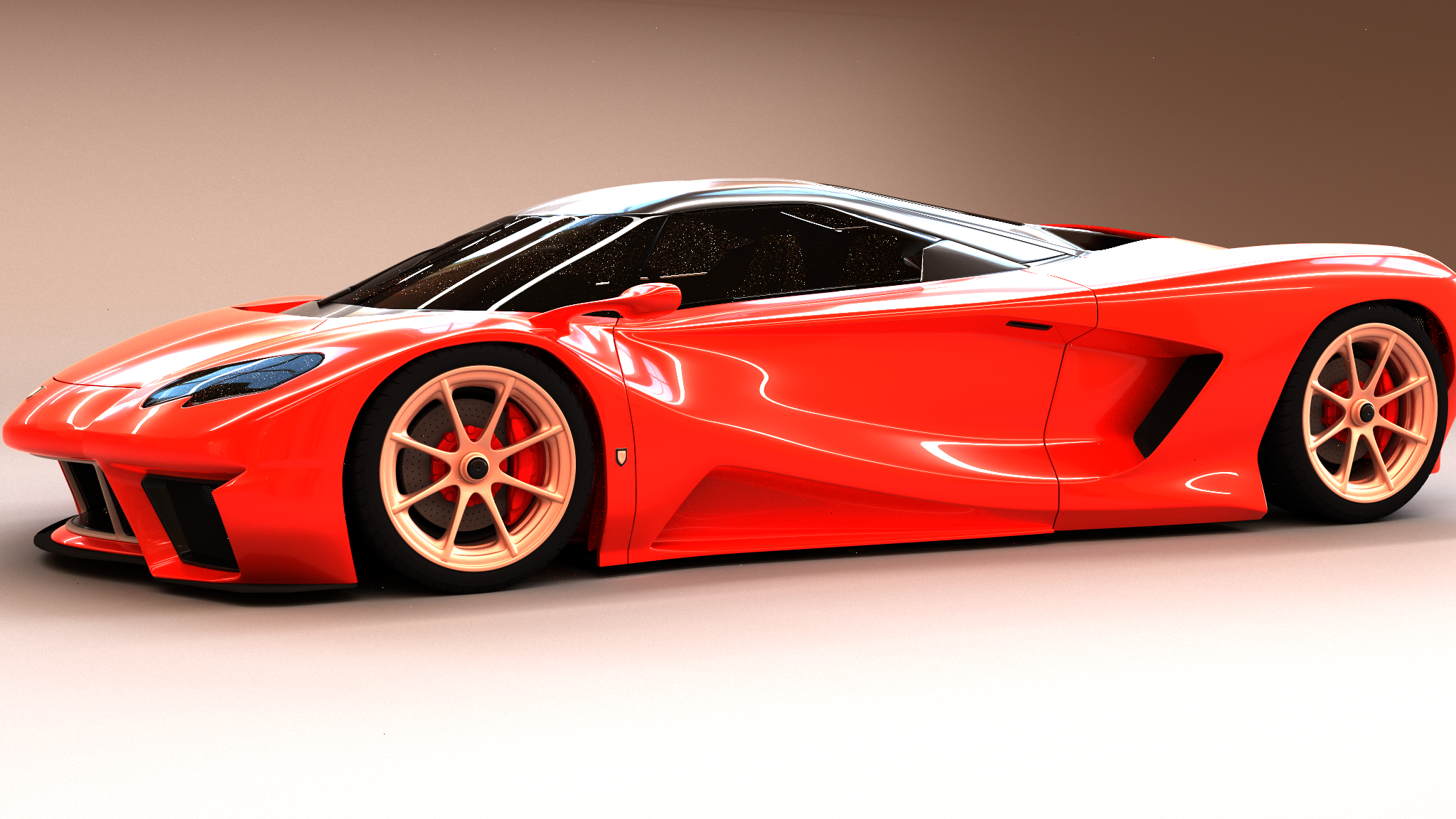
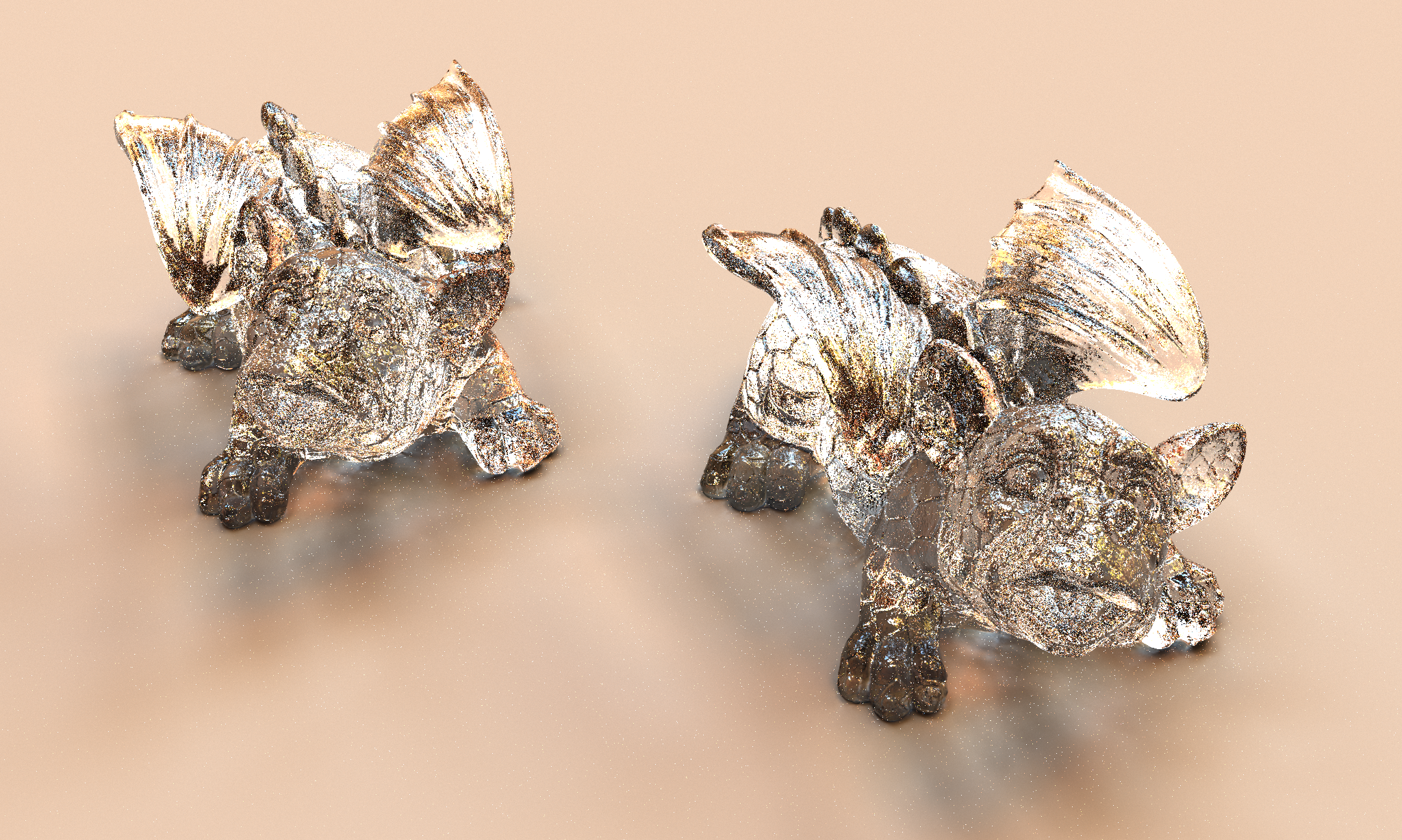
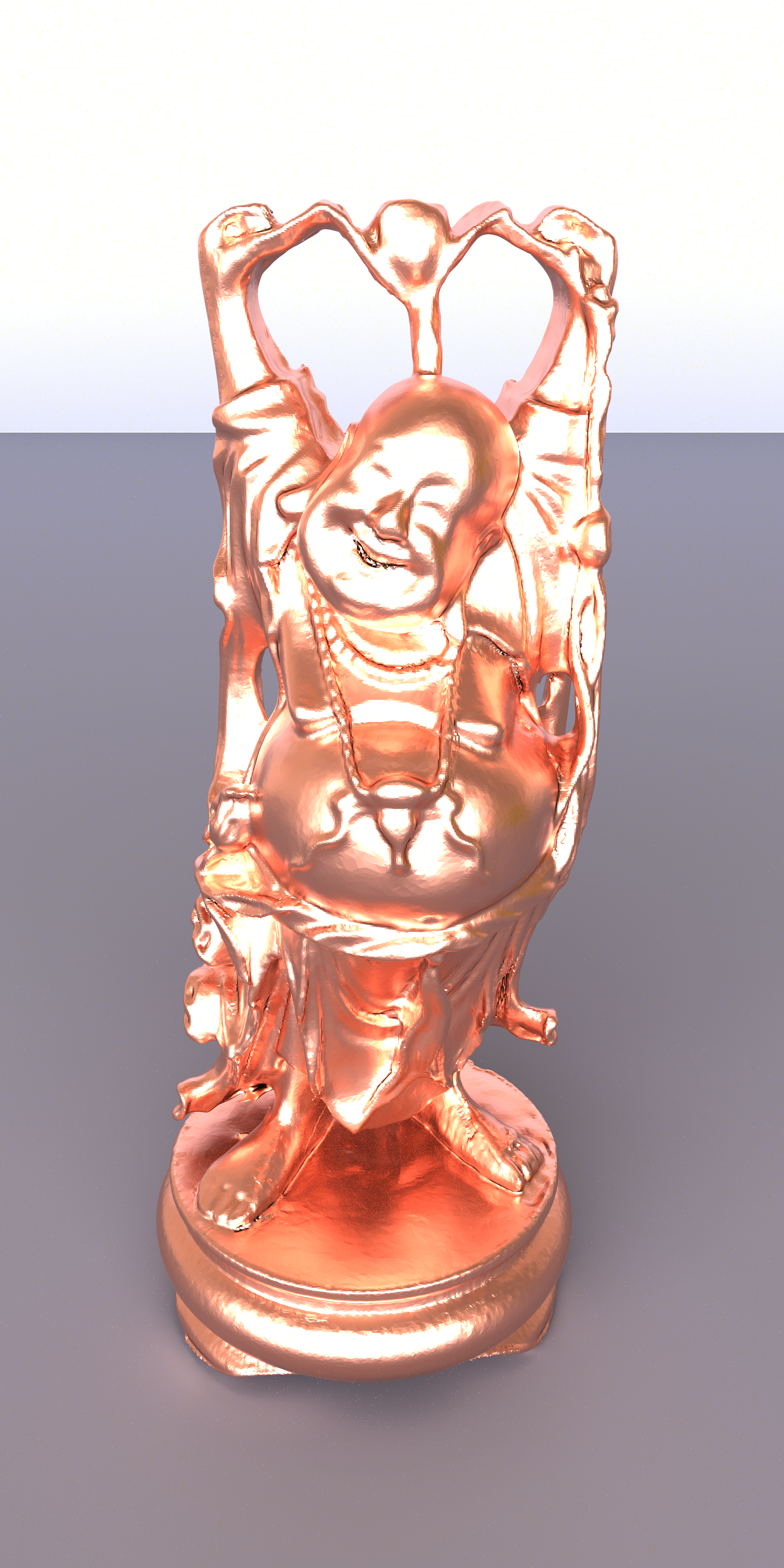
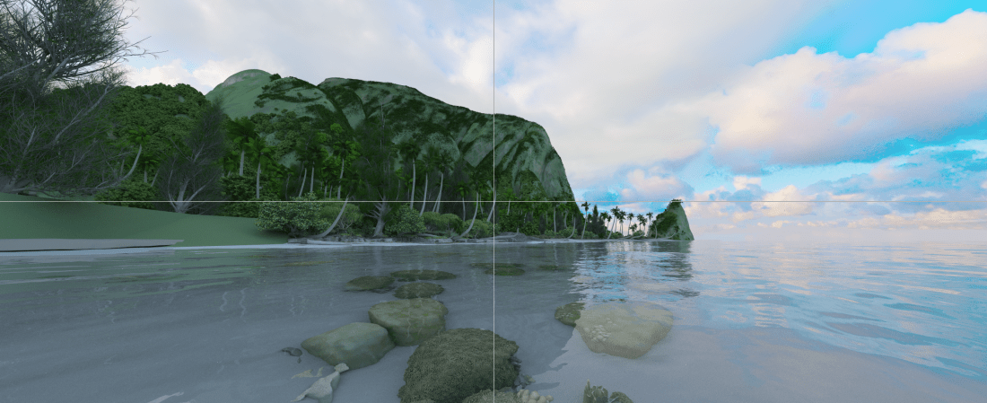
Now before I go into some more detail, here just a few sample pictures that have been rendered with OWL over the last few weeks…. or as I should probably say more accurately, pictures that “have been rendered with several different RTX accelerated renderers built with OWL in the last few weeks”:
Why do we really need something like this?
If you wanted to write a GPU ray tracer a few years ago, you had two options: Either use OptiX, or write your own in CUDA. Today, you not only have much faster ray tracing thanks to hardware accelerated ray tracing, you also have more choice in the sense that you could also use DirectX Ray Tracing, or Vulkan Ray Tracing extensions. With all this choice, the question is why one would need anything more than that.
To fully understand why one would need something like OWL, it is useful to take a look back at OptiX before RTX and OptiX 7 came around: Initially – and up to vertion 6.5 – OptiX was a rather high-level abstraction library, where it was quite easy to get something going rather quickly, by writing the desired closest-hit, any-hit, ray-gen, etc, programs, then define a few “attributes”, “buffers”, and “variables” in the device code that the programs could use. One would create a usually rather simple node graph on the host (that would define, say, a triangle mesh and an acceleration structure), set a few variables to parameterize the device-side programs and geometries, and done. Sure, it still took some time to wrap one’s head around what all these programs were for, and how to map one’s conceptual ray tracer to these ray-gen/closest-hit/etc programs …. but once you had that figured out, the mechanics of creating this “pipeline” of ray tracing programs – and mapping to it the device – was relatively simple. In particular, you wouldn’t even need to know what, say, a “Shader Binding Table” even was (let alone how to build it), or which data structures would need to get built when, etc … OptiX 6 would do all that, fully automatically.
The downside of that approach was that OptiX 6 was pretty opaque: once you started becoming a power-user you might end up with OptiX 6 doing things that you didn’t intend it to do, or at times you’d rather it wouldn’t, etc… and because it was closed source, you could easily end up not even knowing why it sometimes did what it did, or what to do to avoid it. So very easy to get started, but sometimes too opaque for power-users.
When OptiX 7 came around, it made short shrift of this problem, by pretty much stripping away all the “convenience” functionality, all the node graph, etc, and instead exposing the (then newly added) RTX technology on what is pretty much a driver level abstraction (which, by the way, is similar to the DirectX/RT and VulkanRT abstraction levels). In that new “driver-level” abstraction the user has full control over everything, including what CUDA streams get used at what point in time, and which memory allocations happen where, which which type of CUDA memory, etc. This change unlocked a whole new level of performance that users have since made impressive use of, and that was the key behind the last two years’ rapid developments in high-end GPU ray tracing. For a power-user (well, at least for me!), the switch from OptiX 6 to OptiX 7 was an experience that was just amazing, plain and simple.
The downside of this change to a driver level API was that it has become much harder to get started with OptiX (or DXR or VKR, for that matter): instead of setting up a simple node graph on the host, you now have to understand the intricacies of acceleration structures, of setting up build inputs and building/compacting/refitting acceleration structures; of compiling programs and pipelines, building shader binding tables, etc. With OptiX 7 this is still much easier than with, say, DXR or VKR, but for the un-initiated, it can still be daunting…. and even for those that do by now fully understand all these low-level technical details, due to their low-level nature there are a lot of opportunities to shoot oneself in the foot by overlooking something or committing copy-and-paste bugs. This can easily take time that could more productively be spent somewhere else.
What OWL aims to do is help users bridge this gap between productivity and convenience on one hand, and performance and low-level control on the other: Like OptiX 6, it offers a node graph abstraction in which the user can create and parameterize relatively high-level entities like “Buffers”, “Geometries”, “Groups” (ie, acceleration structures), and “LaunchParams”, with OWL then doing all the menial tasks of managing the required device memory, building/compacting/refitting the acceleration structures, setting up launch constants, handling multi-device and async launches, and in particular building programs, pipelines, and, yes, the infamous shader binding table.
While thus clearly aiming for convenience, OWL also borrows a lot of the “give the user control” philosophy from OptiX 7: In particular, OWL is a much “thinner” abstraction layer on top of OptiX 7 than OptiX 6 was: there is no magic compiler technology anywhere in OWL, and all device-side shader code is pretty much exactly the same OptiX code as without OWL (though with a few convenience functions). OWL is also much more “explicit” than OptiX 6 was, in that, for example, it is the user that says when the SBT gets built. Third, OWL is completely “transparent” in the sense that unlike OptiX 6 it is completely open source (https://github.com/owl-project/owl), so the user can always see exactly what it is doing at what point in time … and even if he or she may or may not ever want to touch any code in OWL itself, he or she can still always see exactly what OWL does at any point in time, and what to do to avoid the bottlenecks or crashes. Finally, OWL explicitly aims to allow easy and efficient “inter-op” with CUDA, and one can, for instance, at any type query the device addresses of buffers or the CUDA streams used for a launch, etc, …. so it is, for example, absolutely possible to launch a CUDA kernel that reads from or writes to any of OWL’s data, or to launch into the same CUDA streams used by OWL, to run CUDA kernels asynchronously to OWL launches, etc.
How “real” is this?
The web (or even only the github-section of it) is full of libraries at varying levels of completeness, often abandoned, or doing only exactly what the proejcts’ author needed the project to do, and hopelessly incomplete for anything else. And yes, I’m absolutely sure that there will also be some bugs or missing features in OWL, that simply haven’t been found yet because nobody has yet used it in a specific way that would trigger the respective bug or missing feature. In particular, OWL is not a official “product” with a big team of engineers whose sole job it is to maintain this code – it is a library I’ve originally written because I had need of it myself, and that has simply grown to be much more than that.
At this stage OWL is still relatively new, and will undoubtedly still have some teething problems. However, it is now more than two years in the making, and at least judging from the last few months the teething problems seem to be mostly over. OWL now has been used successfully by different users, and for actually several very different kinds of different applications; in fact, I don’t think I’ve done a single project in the last year that did not get easier by using it, and the list of things that got newly added over the last few months is rather small. To give an idea of how far OWL has come, and what it can already do: here a brief selection of what has already been publicly written about (or is otherwise publicly accessible), and all the pictures here have all been done with renderers that built on OWL.
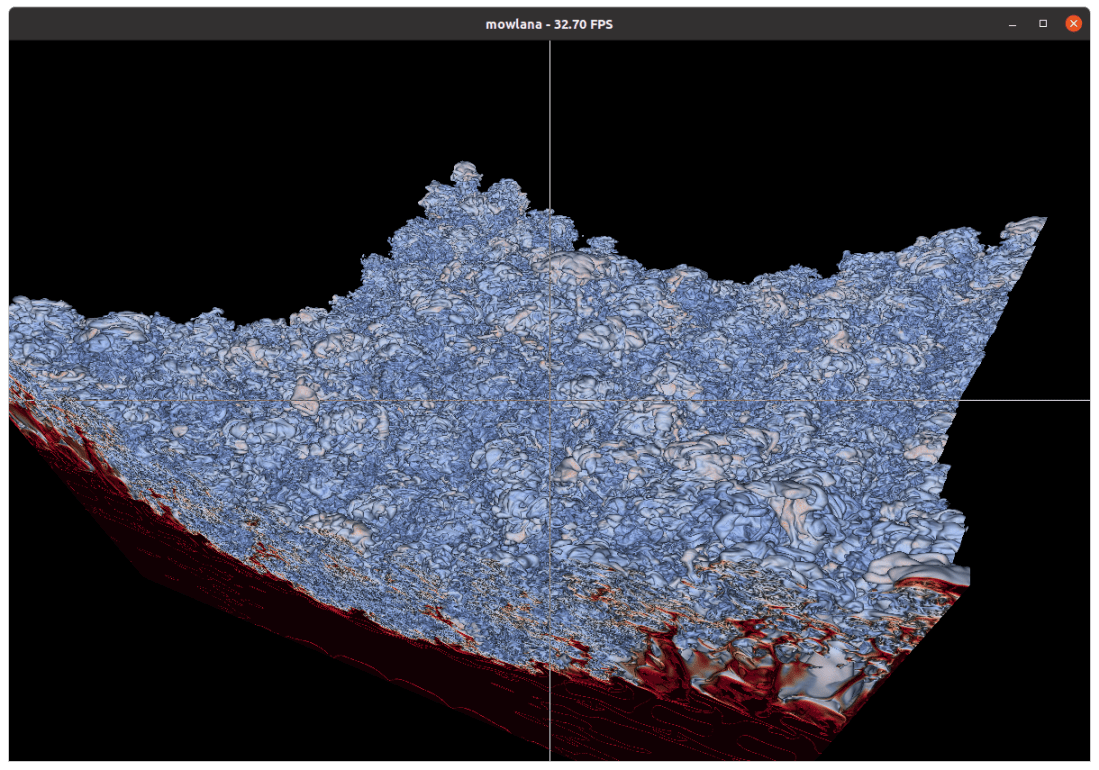
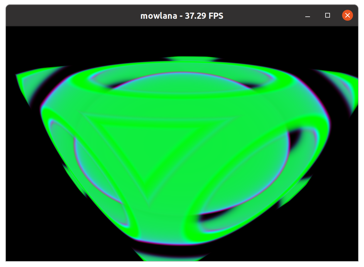
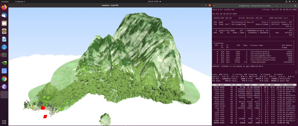
“Mowlana“. Mowlana started out as a sandbox for comparing/stress-testing different rendering back-ends (e.g., OptiX 6 vs OptiX 7), but has since developed into a bit more of “Moana on OptiX” viewer. I’ve recently written about this (https://ingowald.blog/2020/10/26/moana-on-rtx-first-light/), and though it’s clearly still “work in progress” virtually all the work of the last few weeks and months has revolved around things like data wrangling, with the entire OptiX component done by OWL, period.
OWL Samples. OWL itself comes with a few intentionally simple and self-contained samples; though intentionally simple these already demonstrate features like triangle and user geometry, different buffer and acceleration structure types, multi-gpu (pretty much free in OWL), different ray types, multi-level instancing, refitting, motion blur, etc. Here a few screenshots showing a OWL version of Pete Shirley’s Ray Tracing on a Weekend (plus some extensions, just because with OWL it was so easy to add this :-)), a OWL version of our OptiX 7 Siggraph course viewer, and some simple ones with multi-level instancing, IAS updating/refitting, and motion blur:
“Exabricks“: Arguably the prettiest images I’ve been involved in in a while (though most of the credit for the right transfer functions etc goes to Will, Nate, and Stefan…) – our “ExaBricks” Adaptive Mesh Refinement (AMR) Rendering project that we presented last week at IEEE Vis – with all the actual ray tracing and rendering of course done in OWL. (OWL also automatically handled the multi-GPU rendering that this challenging scene could really make use of).
Paper: “Ray Tracing Structured AMR Data Using ExaBricks”. I Wald, S Zellmann, W Usher, N Morrical, U Lang, and V Pascucci. IEEE TVCG(Proceedings of IEEE Vis 2020).
https://www.willusher.io/publications/exabrick
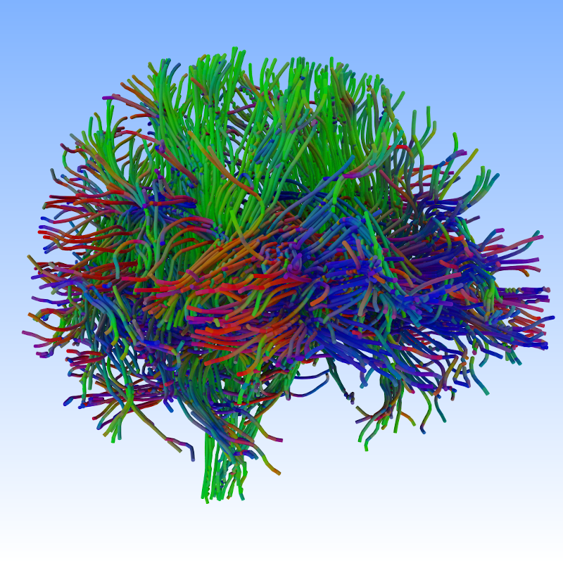
“OWL Tubes”: This started as a proof of concept that RTX ray transforms can also be used to accelerate intersections for thin primitives like tubes and hair (see our HPG 2020 Paper on this through this link) … but even for this rather low-level operation, it was eventually easier to do it through OWL than through OptiX natively. For these pictures, too, all the credit goes to the other authors of the mentioned paper:
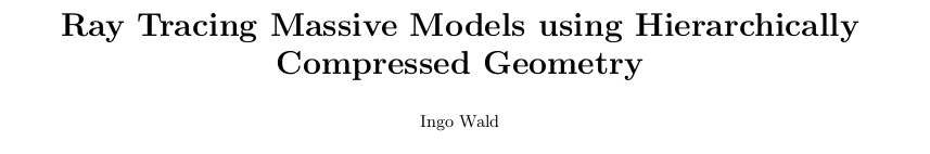
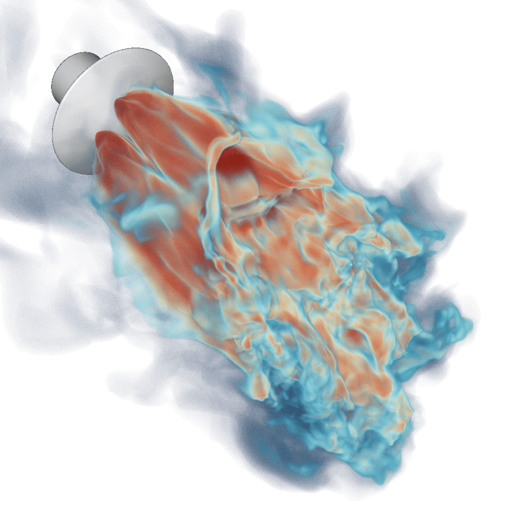
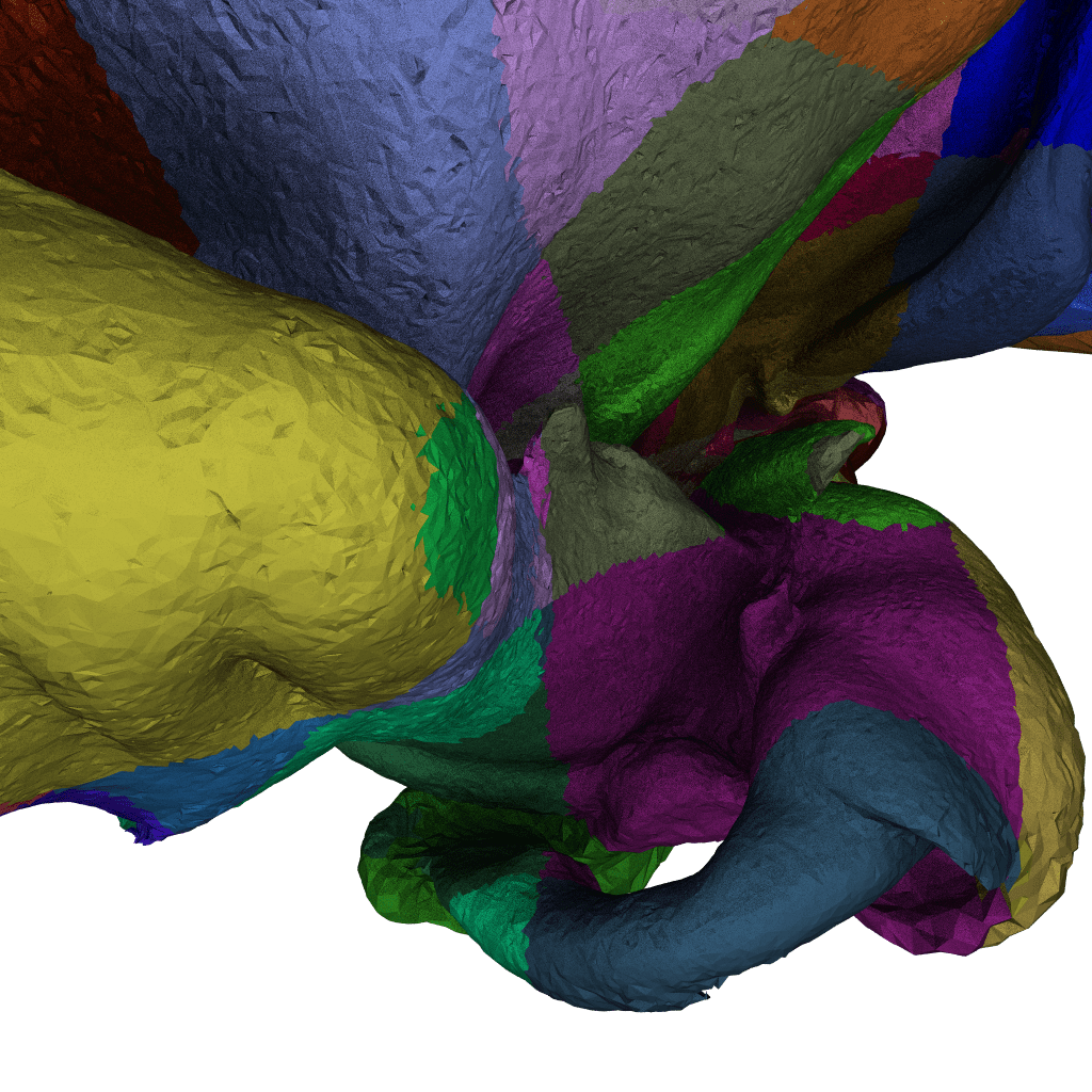
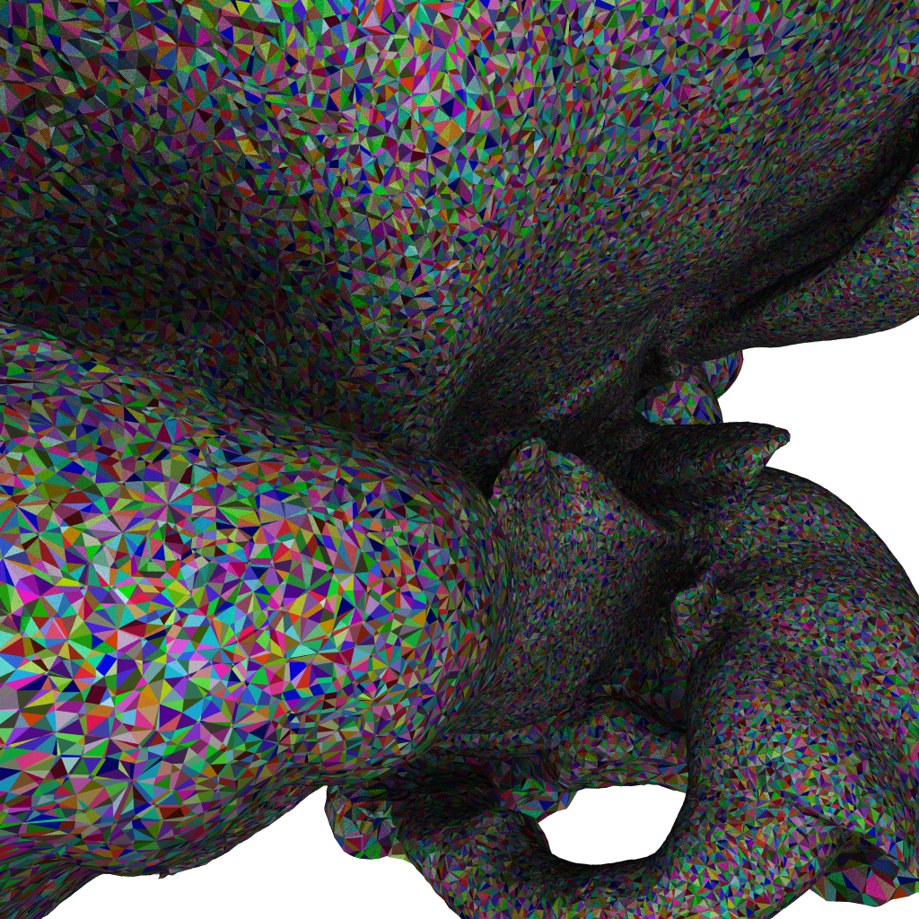
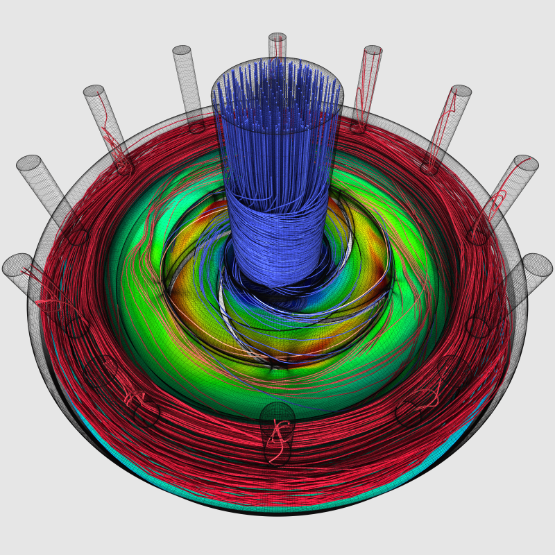
“Unstructured Mesh Rendering”: Though some of the latest results that produced these particular images are not actually published yet, here a few screenshots from our latest unstructured-mesh rendering, on the NASA Mars Lander Retropulsion Study data set:
We also used OWL for some of our recent papers on fast tet-mesh and unstructured-mesh point location (and some applications of that), but I’ll skip these for now.
“OWL Prime, and Primer”: While the “main” interface to OptiX 6 was the node graph layer – with closest hit, intersection, miss, and raygen programs etc – it also came with an additional API that allowed users to set up only the geometry part of the scene, and then trace entire wave-fronts of rays, and get back wave-fronts of intersections. This abstraction comes with a lot caveats (that I will not go into here), but – based on feedback I got – was still quite useful for a lot of users. For OWL, I developed a similar library called “OWL Prime” – though by now I mostly refer to it as “Prime Owl”, as if it was a feathery animal – that offers the same abstraction level, including asynchronous launches, automatic (and async) upstreaming/downstreaming of ray/hit streams (if data lives on the host, etc).
And just to put that library through its paces I also wrote a “little” wavefront renderer (fittingly called “primer”) that, by now, has stolen almost all the shading / material / fresnel / distribution / sampling / microfacet / etc code from PBRT – doing the PBRT shading in CUDA, and all the tracing in prime-owl. Again, here a few proof of concept pics, these ones fresh from Sunday night:
This is clearly still “work in progress” (PBRT isn’t ported in a weekend …), but as a proof of concept it was more than successful: Literally all the remaining work is entirely on the shading/sampling/materials side – I didn’t even have to change anything in prime-owl, let alone in OWL.
I also have some version of Pete Shirley’s “Ray Tracing in a Weekend” scene where all the shading is done on the host (using a literal copy of Pete’s code), and all the tracing is done asnchronously on the GPU (with prime-owl using OWL’s launches and support for CUDA interop to do this, of course).
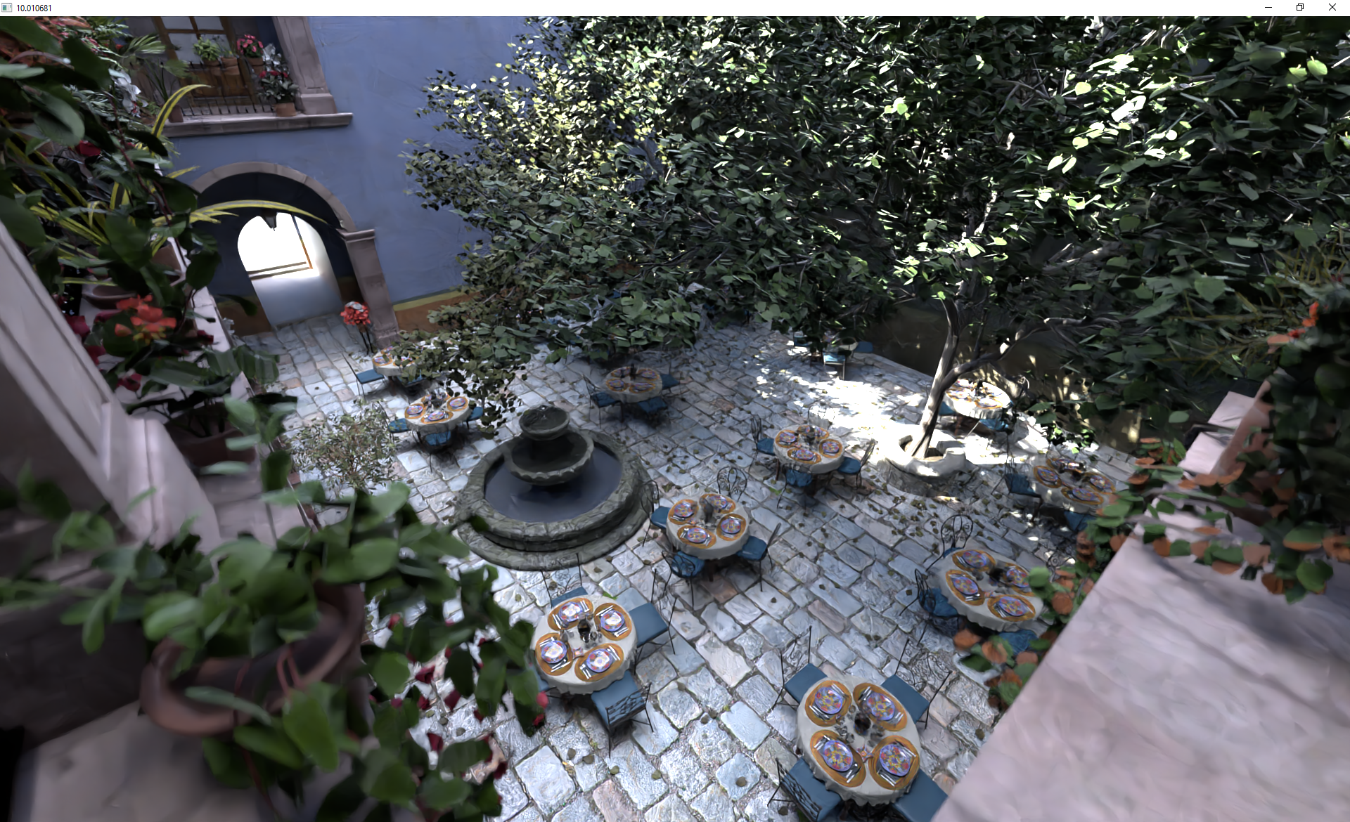
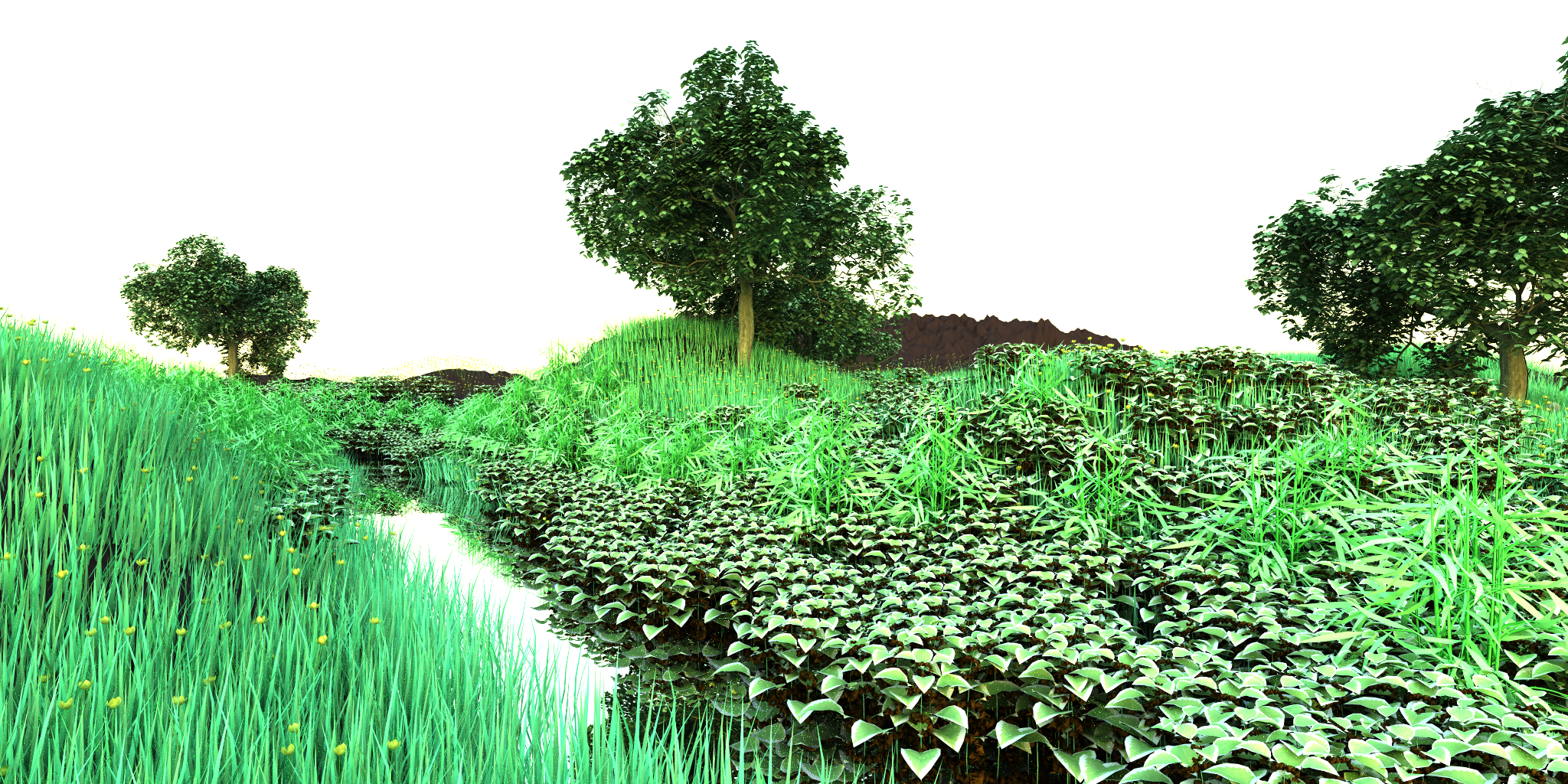
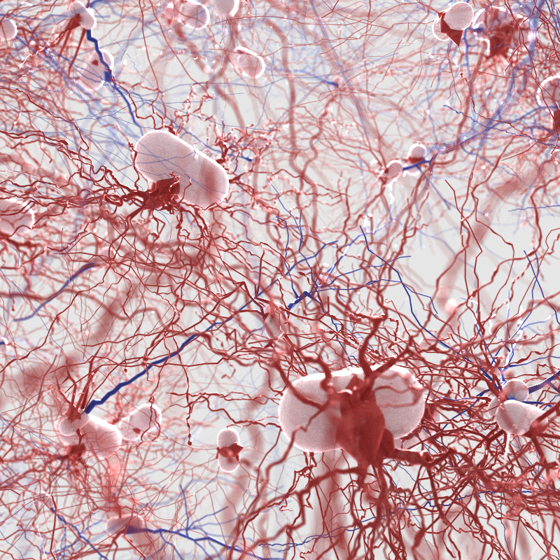
VisII: VisII is a python-scriptable, ray tracing based “scene imaging interface” (ie, a renderer) that allows a python user to easy create, modify, and render both photo-realistic images as well as certain derived images like normals, object IDs, etc. The main use case for this is use in robotics and other AI / Machine Learning based algorithms, where users can easily create high-quality images in python, including the additional “labels” that many algorithms require. Here again a few pictures:
Of particular interest to this post is that VisII was the first renderer that I did not write at least a significant portion of myself; it is almost entirely written by Nate Morrical (latest code is on https://github.com/owl-project/ViSII), and though initially there were certainly things missing in OWL that I had add for some of his more advanced use cases – in particular, I had to add buffers of textures, different texture settings, and motion blur, if I remember correctly – it is nevertheless a non-trivial application that could be done by somebody other than the author of the underlying library… which is always a good litmus test.
There are, in fact, a few more projects using OWL, but for the sake of space I’ll leave those out for now.
Now finally, how does one actually use it??
Oh-kay .. this has been a loong post; there will, eventually, be much more to be written about, but at least for now, I hope this will have given a rough idea of what OWL is, how it works, and what it can already do. If, as I hope, this had made you at least curious as to how it actually works, then your next question will likely be “well, but does this actually look like to a potential user?”.
For that, I had initially written a rather detailed “primer” on all the OWL concepts, with sample codes, etc, but that turned out to be a bit too long for a single post, so I’ll defer that to a later post. For now, all I’ll do is provide a tiny (and obviously incomplete!) example of creating a simple scene of a set of triangle meshes (and a single instance thereof), very similar to the kind of content that the “optix7course” sample would have done. Leaving out all the pieces of loading data, etc, this would look roughly like this:
// declares how device-side triangle meshes look like, used in
// owlGeomTypeCreate, not shown here
OWLVarDecl triMeshVars[] = {
  { "diffuseColor",OWL_FLOAT3,OWL_OFFSETOF(MyTriMeshClass,diffuseColor) },
   ...
};
...
OWLGroup createWorld(host::Scene *scene)
{
  std::vector<OWLGeom> geoms;
  for (auto mesh : scene->meshes) {
    // first, create the vertex/index buffers:
    OWLBuffer vertices
       = owlDeviceBufferCreate(context,OWL_FLOAT,
               mesh->vertices.size(), mesh->vertices.data());
    ...
    // second, create the geometry, and assign buffers
    OWLGeom geom = owlGeomCreate(context,triMeshGeomType);
    owlTrianglesSetVertices(geom,vertices,....);
    owlTrianglesSetIndices(geom,indices,...);

    // third, assign user data (_user_ declared what that is!)
    owlGeomSet3f(geom,"diffuseColor",mesh->diffuseColor.x,...);
    ...
    geoms.push_back(geom);
  }
  // build bottom level accel:
  OWLGroup blas
    = owlTrianglesGeomGroupCreate(context,geoms.size(),&geoms);
  owlGroupBuildAccel(blas);

  // build top-level/instance accel struct:
  OWLGroup ias
    = owlInstanceGroupCreate(context,1,&blas);
  owlGroupBuild(ias);

  //done:
  return ias;
}
Of course, I left out a whole lot of stuff here – context creation, definition of the geometry type, creating a module that contains the device programs, the device-side closest-hit and other device programs themselves, the launch call, etc. However, if you can read the above code then all these other things I left out should be rather simple to use, too. For example, once all geometries and accel structs are built, creating the shader binding table is a single call:
owlBuildSBT(context); // that's it ...
Similarly, assuming a launch params object has already been created, launching a frame is as simple as this:
void render() {
   // note _what_ variables are in the launch params is _user_'s choice!
   owlParamsSetWorld(myLaunchParams, "world", world);
   owlParamsSetBuffer(myLaunchParams, "fb",frameBuffer);
   ...
   owlLaunch2D(rayGenProgram, fbSize.x, fbSize.y, myLaunchParams);
   float4 *pixels = (float4*)owlBufferGetPointer(frameBuffer,0);
   ...
}
Again, I’ve left out a whole lot of stuff; I’ll write a more detailed “primer” on OWL soon, but for this post, all I wanted to do is give you an idea that OWL exists, what it is, and that it is now ready for use.
If you’re interested in learning more: first, have a look at the OWL repo on github, namely https://github.com/owl-project/owl. In particular, OWL comes with a set of samples that are intentionally built in an almost “tutorial” style way, from very simple command-line ones that create a single triangle mesh, to more advanced ones with interactive model viewers, etc; these are all part of the github repo, under https://github.com/owl-project/owl/tree/master/samples. If you just want to get an idea of how OWL works, most of these should be rather self-explanatory, though I’d suggest to start with the simple command-line ones, so you don’t get distracted by any windowing code. And finally, I just started creating a github wiki as well, to provide some pages with explanations about what variables and launch params are, how to use them, etc: https://github.com/owl-project/owl/wiki. Going forward, this wiki will likely become the main entry point for documentation, how-to’s and frequently asked questions.
Wrap up
If this post did entice you to “maybe” give OWL a try, please feel free to do so; it’s completely free and Apache “do-as-you-please” licensed. If you run into issues, or have any specific “but how do I …” questions, most certainly let me know, and/or file an issue on the github issue tracker. And if you end up using OWL as “training wheels” to get the hang of it, and then later-on decide to go OptiX native – maybe even by copying useful pieces from OWL and discarding then rest – then that’s perfectly fine, too. I really do hope you’ll like it – there’s a tremendous amount of work in OWL, and I personally couldn’t imagine not using it any more … so I really do hope others will find it as useful as I do. And finally: If you do anything cool with it, let me know!
With that: back to work 🙂
PS: some links to further info:
PPS: Just because I know the question will come up: OWL stands for “OWL Wrappers Library”, because that’s exactly what it originally started out as: namely, a set of simple “wrappers” that would help with things like GPU memory allocation, up/download, building acceleration structures, setting up build inputs, etc. It just turned out that this abstraction level just wasn’t nearly enough to address what was the real elephant in the room (the beloved SBT…  ), so by now that is a total misnomer …. but it sticks, so OWL it still is.